Category Archives: Articles

Food Blending

Food blending system “USB” is used for mixing of different components. This system are used for preparation directly in the capacity of food compounds or emulsions, for mixing of syrups, cocoa, cakes creams and other types of confectionery liquids. For mixing of products mayonnaise, sauces, ketchups, soups, compotes and other compound foodstuff, and also in the confectionery industry, pharmacological the industry and other types of production for different liquid mixing of components.

food-blending

Process of food blending consists in preparation of ingredients, their periodic dispensing, mixing, compound unloadings, preparation of the mixing camera for the subsequent operations. The present standard defines safety requirement for process of food blending systems manufactaring. Food blending system “USB” is completed with the heat insulation, mixing devices, reducers, shirts for heating, and as the additional equipment, according to the specification of the customer. Food blending system “USB” can have the different volume, construction and the form which is necessary for successful application on production.

Primary benefits of food blending system “USB” are: final product without foliation, for the long period; broad spectrum of applicability to materials; high speed of mixing; variation of volume of loading; operation in hermetic conditions, simplicity and ease in service. Food blending system “USB” manufactured by Globecore provide constant quality of all batch of a compounds, even in switching time of account capacities, shortages of raw materials, loss of power supply or in an improbable case of a failure of one of system components. The ready-made product mixes up in the hydrodynamic ultrasonic adder of compound installation and provides persistence and accuracy of the set analyzer. In the same place there is a flange for sampling. Food blending systems «USB» possess a number of advantages, and first of all it is the whole complete unit of the equipment which is easily integrated into any type of production.

Ethanol Blending

Interest to alcohols is caused by a ratio between their prime cost and their useful properties as gasoline components,  be more specific their ability to increase octane number. As the component to fuels ethanol represents better interest, than methanol as it is better dissolved in hydrocarbons and is less hygroscopic. It was set that the additive of 5% of ethanol to gasoline doesn’t lead to deterioration of operation characteristics of the engine and doesn’t require regulation. Essential lowering of bursts essential lowering of CO and hydrocarbons. Optimization of gasoline composition looks not such complex challenge. It is really possible by using of “USB” (Ethanol blending system) which are manufactared by the GlobeCore company. Ethanol alcohol concentration of 92-96% blends with gasoline using GlobeCore company Ethanol Blending system. Time of phase stability of a compound makes not less than 6 months.

By the GlobeCore company it was developed and delivered on a mass production a number of Ethanol Blending Systems “USB”  which are applied to ethanol blending and to mixing of different liquids. Blending systems are as stationary and mobile execution. Manufacture of Ethanol Blending Systems “USB” is coordinated with the customer and generally made under personal requirements of the customer depending on required compoundings and receiving the final product.

Ethanol blending is used in a hydrodynamic blender “USB”. This process allows to present all components at the same time in coordination to a formula.The benefit of this technology is in the following: each element dosing accurate control, substantial reduction of batching process duration, no need in batching vessels for finished product homogenization. In the ethanol blending process at stream mixer the consumption of each element are controlled for the purpose of providing completed product outlet with parameters wich corresponds to the formulas.

Blending

Liquids blending processes are extensively relates to human life. For example we could meet these processes in the laboratory chaotic advection researches, in oil processing branches, chemical, industrial and even in the food industry. Passing speed, quality of a compound and expense of energy are undoubtedly one of defining factors in developing process of blending system.

Despite that engineers spent huge time on development of the modern blending systems, still there are manufacturer plants compare for quality and homogeneity of a ready compound without the long foliation in all volumes and minimum electrical expenses. As all liquid components after all have distinction of property on density, salinity, viscosity and color. The main objective of blending process consists in reaching simple distribution of components in a principal component.

When liquid with high intensity gets to processing by ultrasound, sound waves extend in liquid and lead to formation of high pressure cycles which called compression and low pressure which called discharge with a speed depending on frequency. In the discharge period high-intensity ultrasound waves create small volume bubbles or spaces in liquid. Bubbles grow to the sizes that they can’t absorb energy any more, they expose during a compression. This phenomenon calls cavitation.

Flow of liquid which passing “USB” blending system gets to the cavitation zone. Frequency of pulses is caused by properties of “USB” blending systems and it is located in the range from 400 to 35 000 Hz. All flow of liquid passes through a zone of highly effective cavitation.

turbine

In the process of cavitational bubbles explosition for very short time (less than 1 microsecond) pressure more than 1000 atm develops. Due to big stability of operating frequencies, high homogeneity of a ready-made product is reached. Blending system  ”USB” is constructed and selected for support of the minimum pressure differential and maximum reliability. Blending systems “USB” which manufactared by Globecore company are equipped with the controler with unique self-training algorithm which instantaneous reacts to changes of process conditions or quality of raw materials. Components are continuously dosed, and their ratio is permanently regulates during product production to provide optimum quality and minimum loss.

USB

BioDiesel Blending

Rates of use of biological raw materials in a fuel sector are achieved by fast turns. Leading positions in production of bioethanol, absolutely are belonged to Brazil and the USA, development of BioDiesel blend fuel solid grows in the different European Union countries.

What is the biofuel? Biofuel — this fuel doesn’t possess a benzol smell and is made from oils as raw materials for which the plants improving a structural and chemical composition of soils serve. Different vegetable oils can be raw materials for receiving the biodiesel: sunflower, rape, soy, palm, coconut, corn, mustard, and also animal’s fat in arbitrary ratio. One of striking examples is the biodiesel. The biodiesel – the fuel of diesel engines allowing favorable changeover to mineral oil product. Rape oil which is base of biodiesel , it is a subject to processing by methanol in a compound with the catalytic agent, finally receive about 90% of diesel biofuel. By means of additives and BioDiesel Blending equipment bring diesel biofuel to a trade quality which responds all international standards. This fuel could be  possible use as independently, and in a compound with diesel fuel in arbitrary ratio.

blending

Essential operation and optimization of BioDiesel Blending systems  is carried out by engineers of the GLOBECORE company. They developed and delivered on a mass production a number of mixing installations under the name “USB” of compounding of fuels and any liquids (from two to five components) in a flow including with components of a phytogenesis and bioethanol. BioDiesel Blending systems are issued in several types as stationary and mobile execution (the mobile can be mounted on trailers and semi-trailers, vans and railway platforms and as any other mobile means). Customer wishes and requirements are considered in case of manufacture depending on necessary compounding and a type of the final product. BioDiesel Blending is capable to make any class of fuel: diesel summer fuel, diesel winter fuel, diesel Arctic fuel, high-octane for Euro-4, Euro-5. The primary and indisputable benefits of technology of receiving compound fuels economic profitability belongs.

Chemical Blending

Chemical blending is one of frequent kind of chemical process that is commonly used in chemical application. The procedure of blending chemical can potentially save chemical manufacturers time, labor, inventory, and transportation costs. Organic and inorganic chemicals can be blended. Chemicals could be blended in liquid form to a variety of pH levels and viscosities.Blending chemical services consist of multi-component blending chemical, homogenization, liquid blending, high Intensity and liquid powder blending.

For manufactaring of blending chemical system “USB” the most important the choice of materials and compatibility of components. Not for the last part is assigned to the principle of blending chemical system operations and stability of materials. Blending chemicalsystem “USB” are used in case of cultivation of substances, and also during the mixing and preparation of different chemicals, for example in case of cleaners production and detergents. At the request of the customer we make diagrams for specific distribution of products. Productivity and automation level of blending chemicalsystem is defined depending on its components. Blending chemical systems “USB” supplies blending chemicalequipment for the worldwide chemical industry. Globecore has designed and manufactured industrialblending chemical systems “USB” for over 12 years. The blending chemical systems “USB”is equipped with the high-tolerance additives batching electronic system with digital display, allowing to set the additives dosing extremely accurate.

USB_system

Blending chemical process is used in hydraulic blender. This process allows supplying of all components simultaneously according to the set formula to batching collector. Through the collector finished product is delivered to storage vessel. The advantage of such technology is in the following: each component dosing accurate control, substantial reduction of batching process duration, no need in batching vessels for finished product homogenization. In the course of blending chemical process at stream mixer the consumption of each component are permanently controlled for the purpose of providing finished product outlet with steady quality parameters, set with the formulas.  Finished product, received from stream mixer, has homogenizing structure and component content in accurate compliance to set formulas.

USB_blending

Fuel economy

Fuel economy is a constant factor both for motorists and large research facilities. The increase fuel price make it necessary to search for efficient methods, which can help save money. An average car may have an annual mileage of several thousand miles. In term of fuel expenses, it is quite an amount which may be costly for any budget, be it a small business or a family. The internet has a wealth of information on fuel economy, and this is an attempt to look at them in more detail.

In modern European vehicles, nominal and actual fuel consumption are practically identical, which cannot be said about older vehicles. Those consume a lot more fuel. In real numbers, European cars consume 4 to 6 liters of petrol per 100 kilometers even in city traffic.

Hydrogen and Brown gas. If gasoline is used together with cheap alternative fuels, economy is very real. At this time many vehicle manufacturers are researching ways to develop electrolytic generation of hydrogen. Such devices are called Brown gas generators or hydrogen generators. They generate not the dangerous H2, but a more safe compound, called Brown gas, HHO, made in catalytic electrolysis cells. The gas is then injected with fuel and air into the cylinders, saving fuel. This is due to the reduction of the amount of fuel mix fed into the cylinders and intensification of the combustion process. All processes from generation of gas to optimization of the mix are completely automated and are managed by a single processor.

Water-gasoline emulsions. First experiments in saving fuel by forming water-fuel emulsions began in the 1970s. This is when the research into increasing economy by injecting water into the cylinder along with the fuel. Back then there were no electronic control systems reliable enough to commercialize the technology. With time, the process was automated. Such devices may be installed either on injector or carburetor engine.

Water enters into the manifold through the nozzle. There it is mixed with air, forming micro drops. After fuel injection, these droplets become covered with a thin fuel film, increasing the fuel’s surface area. In the result the combustion of the fuel is improved. Combustion products and water vapor move the pistons.

For implementation of such systems it is enough to correctly set up the injection system or improve the carburetor engine somewhat.

Projected economy with the use of such systems is up to 30% or more, if the vehicle run on low octane fuel.

Oxygen ionizers. Again, the modern electronic control systems allow to use oxygen ionizer. The latter enters the combustion chamber and polarizes hydrogen molecules, freeing active oxygen radicals. The fuel-air combustion in the chamber is quite intensive and happens faster. Manufacturer estimate 8 to 10% fuel economy and potential ability to switch from 95 to 92 octane petrol, saving 5 to 7% more.

The above methods require complex technology to implement. However, there are simple general recommendations, tested and tried by motorists. Although the economy is not that significant, they are still worth following.

Driving style. Smooth driving without pushing the pedal to the metal saves fuel. This is easy for drivers with automatic transmission. For manual transmission, the driver has to keep track of engine rpm and shift accordingly many times a minute without the help of automation.

Air conditioning is another factor. All extra devices are powered by the engine. Air conditioning consumes significant amount of power, so it should only be used when it is really necessary. Never turn AC on with open windows.

Drag. When the vehicle is moving, the oncoming air creates drag, especially with open windows. In some cases it is better to turn on the AC than to pull the windows down.

Tire pressure. This should be kept within the limits specified by the manufacturer. Higher pressure reduces fuel consumption, but reduces tire lifetime and comfort. Overpressure is not recommended: the saved fuel will probably not cover the cost of tire replacement.

Lighten the vehicle. Every pound in the trunk increases fuel burn.

The gap between spark plug electrodes should be kept at manufacturer specified maximum. This is usually 1 mm. The correct gap improves combustion and reduces fuel burn.

Diesel fuel purification: the price of centrifuge

During centrifuge separation of diesel fuel, a solid particle or a water droplet experiences the centrifugal force directed away from the center of rotation. At the same time, the particles may also experience the buoyancy force in the opposite direction (to the center of rotation). The difference of centrifugal separation from gravity separation is that the acceleration does not originate from gravity forces, but from centrifugal acceleration. In this case, the gravity force is much weaker than centrifugal and can be neglected. Particle movement is also slowed by drag, caused by the liquid medium.

There are two types of systems used for centrifugal force for purification of diesel fuel: stationary and rotary. In the former system, the flow of fuel rotates in a stationary apparatus. In the latter, the fuel rotates together with the rotor of the machine. In scientific literature the former are also named hydrocyclones, and the latter are referred to as centrifuges (centrifuge separators).

The centrifugal force in hydrocyclones is generated by the rotation of the flow of diesel fuel in stationary tank. The latter may have various shapes: conical, cylindrical or cone-cylindrical.

The most common hydrocyclone system is when flow swirling is caused by tangential entry into the system. Such units are used in the United States for polishing of light oil products and liquefied gases in main oil lines. Hydrocyclones ensure removal of particles as small as 20 micron.

Hydrocyclones have no rotating parts, therefore such systems are reliable and do not require regular maintenance. The main drawback is the reduction of efficiency if the diameter of the tank is increased. This dictates the solution of combining several hydrocyclones of small diameter into a single system, which, together with collectors, is a complex structure.

Another drawback of hydrocyclones is a significant hydraulic resistance, caused by a sharp 180o change of flow direction. To reduce this effect, flow straighteners are used to arrange the outflow form the cyclone. However, the use of straighteners complicates the cyclone’s design and can reduce purification efficiency due to the change of hydrodynamics in the flow.

To further reduce the losses, direct flow cyclones may be used. These feature swirl devices. It should be noted that such cyclones are less efficient than the previously mentioned counter-current cyclones. This is due to the fact that fuel flow carries some foreign particles away.

There have been attempts to apply cyclones to remove free water from diesel fuel. Such attempts were not very successful, since the velocity of water droplets is significantly lower than in centrifuge separators, limiting dehydration efficiency.

Complete separation of water from diesel fuel is impossible, but its efficiency can be increased in double stage cyclones.

As was mentioned before, centrifuges are systems in which centrifugal forces are generated by the rotation of the moving part, the rotor. It can be driven mechanically, electrically, hydraulically or pneumatically, or even by the flow of diesel fuel.

There are many centrifuge models today, which can differ significantly, both in terms of design and assembly.

There are thick and thin layer centrifuges. They can also differ in terms of diesel fuel movement, which can be parallel to the rotor generating line, in the cross-section plane, at an angle to the axis, in a helical line, etc.

Thick layer centrifuges are rather simple. The rotor is a hollow cylinder. Diesel fuel may move either along the axis of the cylinder or perpendicularly to it. Such unit are mostly used for coarse purification of diesel fuel from larger particles. Smaller particles may be easily carrier away by the flow, not being able to reach the wall due to large distances between the particles and the rotor.

Thin layer centrifuges offer better purification of diesel fuel from solid particles. Their rotors are divided into separate chambers with radial size much smaller than in thick layer centrifuges. This shortens the trajectory of the particles. Efficiency of purification in such devices is also higher due to less pronounced slip of diesel fuel against the wall of the rotor.

Thin layer centrifuges may be cylindrical, conical, helical and multifillar helical.

Centrifuges with spiral and conical insets separate contamination consecutively in all chambers through which the fuel passes. Flow rate is significant, which means that some particles may be carried away by the flow.

Centrifuges with helical inset take diesel fuel into all chambers simultaneously. Then the fuel moves axially, similar to a centrifuge with cylindrical insets. The advantage of these devices is a simpler rotor manufacture technology and almost no slipping of the liquid.

Diesel fuel is supplied along the whole rotor length in multifillar helical centrifuges. The flow velocity in this case does not exceed limits, therefore there is no slipping of liquid relative to the rotor, while contamination removal is simplified. The drawback is a more complex rotor design compared to the other centrifuge types.

Centrifuges with conical rotor insets are also widely used. The movement of liquid occurs along the generating line of the body. A model with a full conical rotor does not efficiently utilize all of its volume, so conical plate centrifuges have been designed. Unfortunately, contamination may also be carried by diesel fuel.

Centrifuges with conical plates are also referred to as purifiers. They are used for dehydration of diesel fuel. Separation of water from diesel fuel in this case is quite efficient, and separate phases are removed from the rotor separately, This is due to a gravity disk in the rotor. It fixes the position of phase separation boundary and creates a hydraulic lock in its upper part.

Speaking of diesel fuel, which has higher density, removal of water is problematic. The main difficulty is that the shift of phase boundary in the direction of rotor axis. In general, removing water from high density fuel by regular methods is difficult, if at all possible.

Removal of contamination from diesel fuel with centrifuges is realistic with low hydraulic resistance and constant throughput. This is why in general centrifuges are widely accepted in purification and dehydration of diesel fuel.

General advantages of centrifuges in comparison to other diesel fuel purification methods are as follows:

  • constant throughput and hydrodynamic resistance;
  • ability to operate with significant pressure drop;
  • low sensitivity to diesel fuel flow fluctuations;
  • self-cleaning capability.

The drawbacks are as follows:

  • complex design;
  • generally complicated purification process;
  • the need for qualified servicing;
  • the need of external power source;
  • low throughput.

This last disadvantage is probably the most significant, as it makes this type of equipment impractical for processing of large volumes of fuel.

Cheap purification of diesel fuel

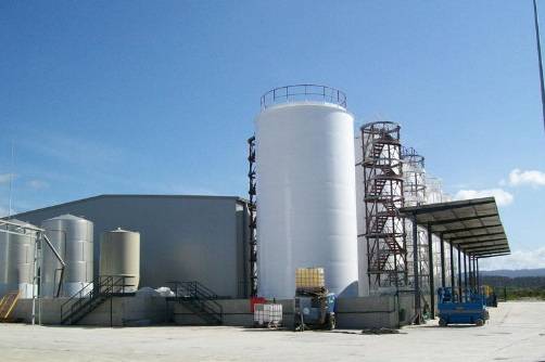
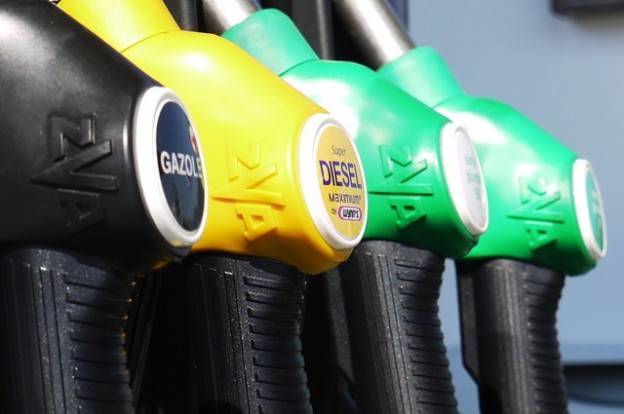
Speaking of diesel fuel, a good place to begin is probably the fact that it is one of the most widespread motor fuels for various vehicles, both land-based (automobiles, tractors, locomotives, tugs) and maritime. Diesel fuel production takes up to 30% of total crude oil produced in the world.

Diesel fuel powers internal combustion engines, sensitive to various contaminants, just as any fuel system. Therefore diesel fuels must comply with certain regulations.

The higher the quality of the fuel, the better the engine operates. Engine’s efficiency is reached due to the anticorrosion properties of diesel fuels. Since these fuels are well purified from contamination which could cause metal corrosion, such contaminants are not a factor. Corrosive activity of fuels is more due to the presence of alkali and mineral acids, water, organic acids and sulfur compounds.

The worldwide environmental deterioration forces many countries to tighten environmental requirements to fuels. Due to the need for reliable and efficient operation of modern vehicles, there are strict requirements to the composition and properties of diesel fuel. Most importantly, these regulations concern the harmful emissions into the environment.

Such emissions include sulfur and ash, as well as polycyclic hydrocarbons. Sulfur was mentioned first for a reason. Sulfur and its compounds are one of the most environmentally hazardous components of diesel fuel.

Publications concerning fuel often use the word sulfur meaning its various compounds: disulfides, sulfides, mercaptan sulfur, thiophane and thiophene.

The hazard of sulfur to internal combustion engines is not only in corrosion, but also the formation of engine sludge. It forms due to combustion of sulfur compounds and can cover the engine with solid and dense film. This is obviously harmful to fuel system. If the need to clean the engine is neglected, the engine fails. Sludge may also contaminate oil. Due to the direct contact with engine parts, the parts wear down, piston rings being the most vulnerable.

In such conditions, the manufacturer of diesel fuel must solve the traditional problem of most industries and productions: how to supply fuel of high quality, compliant with all environmental regulations with minimum costs.

One can find many publications on the web dealing with “cheap diesel polishing”, but not many comprehensively describe methods of quality improvement and polishing of diesel fuel, touching instead on more specific issues. Let us take a broader view of the problem.

Special additives are used for improvement of fuel quality. They are used if the content of sulfur in the fuel is too low. We have spoken of the harmful effects of sulfur, however, if the amount of this substance is insufficient, the fuel’s lubrication properties suffer. This is when additives come into play.

Since the amount of diesel fuel consumed grows annually, the assortment of additives also increases.

The most popular today are the anti-gel, cetane-improving, anti-wear and PPD additives.

Anti-gel additives improve quality of diesel fuel. These additives eliminate crystallization of paraffin in lower temperatures. Without this additives, fuel may become cloudy. This additives serves two purposes: removes water and improves solidification point of fuel. Fuel must be heated before adding anti-gel additives.

The purpose of anti-wear additives is self-explanatory. They are required to improve the fuel’s lubricating properties. They form a protective film on contact with a metal surface.

Cetane number is an indication of the fuel’s combustion ability. Certain additives improve that characteristic. High cetane number improves the fuel’s startability, which is important during cold start of the engine. This type of additives also helps to reduce the amount of harmful emissions in the exhaust.

PPD additives allow summer fuel to be used in winter. The use of PPD also improves the fuel’s lubrication properties, which in many respects influences the lifetime of the fuel system and its components.

There are several chemical and physical methods of sulfur removal.

Sulfuric acid processing involves mixing the fuel with a small amount of 90-93% sulfuric acid. The process runs at normal temperature.

The process results in two substances: purified product and acidic sludge, containing the undesired waste. In general sulfuric acid treatment requires a lot of reagents and is quite cumbersome. Acidic sludge can then be used for production of sulfuric acid.

The drawbacks of the sulfuric acid treatment cause transition to better methods: extraction and hydrotreatment. In future, the acidic treatment may be used for production of white oil, since the large consumption of reagents is not profitable for companies.

Adsorption processing involves bringing the oil product in contact with adsorbents, e.g. silica gels or bleaching clays. They absorb resins and nitric compounds which should be removed from petrochemical products.

Bleaching clay is a natural material with highly pronounced absorption ability. They can decolorize various substances. Until recently, the drawback of this method was incomplete adsorbent regeneration.

Selective polishing methods involve various solvents (nitrobenzene, liquid sulfur dioxide, furfurol, dichorene ethyl ester), which selectively dissolve the harmful substances in an oil product. The main drawback of this method is its inability to restore solvent and its loss. Selective polishing is not widely used for diesel fuel, this method being reserved mostly for oil purification.

Hydrotreatment is used for production of low-sulfur diesel from high-sulfur oil. In the process of hydrotreatment, organic sulfur, oxygen and nitrogen compounds are destroyed. The drawbacks of this method are the high temperature (around 380-420ºC) and pressure (up to 4 MPa), and equipment complexity.

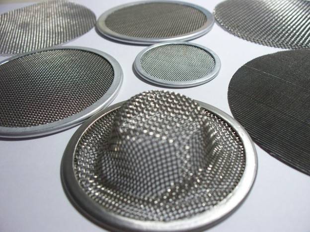
Membrane purification allow to remove sulfides, thiophene, disulfines, mercaptans etc from diesel fuel.

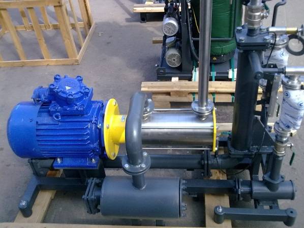
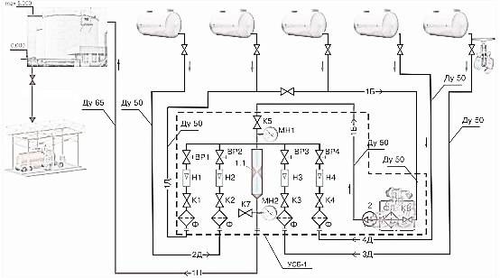
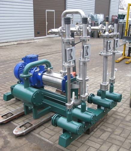
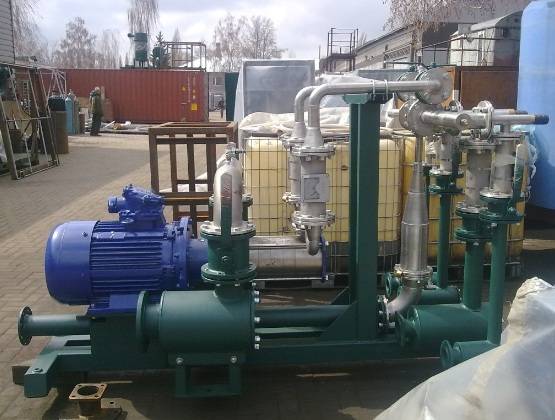
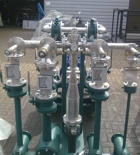
The above are the primary methods of diesel fuel polishing. The selection of a method depends on initial fuel contamination and the required degree of purification, as well as financial considerations. One of the solusions is high quality equipment, proven in the oil product purification market. One such product is GlobeCore’s UVR-450/16. This system can be successfully used for purification of diesel fuel, as well as gas condensate, gasoline, kerosene etc. The UVR-450/16 can also purity industrial, turbine and other types of oil. By purchasing such equipment you become an owner of a highly productive mini-plant, aimed at a wide spectrum of processes in oil product polishing and regeneration.

Fuel purification filter

A fuel filter consists of a case containing a special filtering element. They are classified depending on their purpose, location, fineness, design, principle of operation and regeneration type.

The main purpose of the filter is to remove solid particles and/or water from oil. In terms of location, filters can be stock, installed and supplied with the engine, or used in the process of fuel preparation. There also filters for bunker fuel facilities.

In terms of filter material, there are mesh, fiber, slot, fabric, metal-ceramic, pa,per, plastic and cardboard filters. This list is likely incomplete, since new materials come into use all the time for better purification of oil.

Depending on the way of contaminant capture, there are surface and depth filters.

The former capture contaminants on the surface of the filtering material. Such filters have a large cross section area at fuel inlet. The filtering element is usually cardboard, fabric, paper or similar material.

The latter differ from surface filters by capturing contaminants not only on the surface, but also throughout the volume of the filtering material. They have smaller cross section area, but thicker filtering material (over 20 mm usually). Materials used are thick cardboard, metal-ceramics, felt, fibers or plastic.

The advantage of depth filters is the ability to capture particles of varying size. Devices made of fibrous or granular materials tend to form through channels. Some fuel may pass through them with insufficient purification.

Depending on the number of uses, filter can be single or multiple use. The former operate for a certain amount of time and must then be replaced. The latter can be reused, obviously, after rinsing or some other form of reactivation. The drawbacks of depth filters are the time required for purification, and in some cases impossibility of filter restoration.

In terms of fineness, there are fine and coarse filters.

Fine filters must not let through particles from 1 to 20 micron. This allows for normal operation of engine and fuel system.

Coarse filters are used for removal of 80 – 100 micron particles. Their main task is to guarantee normal operation of a fine filter.

The use of diesel fuel compliant with norms and regulations in terms of solid particles and water content, the stock fuel purification devices of the engine are usually sufficient. However, in some cases fuel quality is an issue and may require additional filters (separators, inline filters) in the fuel preparation system.

Fuel purification

There are quite a few methods of removal of water and solid particles from diesel and motor fuels. The most wide spread methods are settling, centrifuge separation and filtration. Without a doubt, all the methods have both advantages and drawbacks, therefore the research into new methods of fuel purification, chemical and physical, is ongoing. These methods can be divided into one-time and continuous.

The methods of the first group use preliminary treatment of fuel. In the general case, the process is performed by hot water wash or steam purge. The need to use water is dictated by its properties as a surfactant, which can remove most contaminants from the phase boundary between fuel and water. In turn, to completely remove water after the wash, de-emulsifiers are needed. This method does not allow to completely remove contaminants from the processed liquid. Particles smaller than 3 micron mostly remain in the fuel.

This is not the only method. Hydrodynamic method involves passing fuel at 21 – 35 MPa pressure through a special conical valve with reduction of pressure to atmospheric. With the rapid change of velocity and pressure, asphalt and tar are destroyed. The drawback of this method is that nonorganic solids are not destroyed, and the total amount of contaminants in the fuel does not change. However, the size of contaminant particles becomes smaller, which allows to eliminate the risk of rapid clogging of filters, pipelines and nozzles.

Fuel can also be purified by sound waves. In this case, the particles become larger instead of smaller due to acoustic coagulation and can then be filtered out.

Electric separators can remove water from petrochemical fuels. Electric field cases water droplets in the fuel to coagulate, and these droplets can then be separated by gravity or centrifuge.

Physical and chemical methods of one-time water removal from fuel are complicated and cumbersome, even through they are quite efficient. They rely on filtration through adsorbents (charcoal, zeolite, silica gel and alumina gel).

Long-term physical and chemical methods are relatives simpler. They maintain fuel purity for storage and transportation, as well as operation. The method involves injection of small amounts of special additives. Their influence remains constant from the moment of injection to the moment of combustion in the cylinder. Known additive spectrum is quite wide. They limit or prevent corrosion of engine parts, prevent formation of tar, coagulate solid particles etc.

Method selection depends on the specific requirements to fuel.