Category Archives: Petroleum blending

Petrol: Additives and Coefficient-Factor

Gasoline is one of the most expensive sources of energy.  The process of its production is very complicated and includes primary and secondary stages of oil processing at refineries as well as the introduction of various additives.

In practical terms, oil refineries use such additives as MTBE (Methyl tert-butyl ether) and ETBE (Ethyl tert-butyl ether) to obtain gasoline with defined characteristics.  In general, additives constitute not more than 8 to 10% of the total amount of substances in gasoline.  Of course, the price of the finished product is heavily influenced by the price of the additives.

It is therefore, oil refineries, as well as traders, that find it very important to price the additives in a proper way.  Nowadays, the coefficient-factor helps to indicate the price ratio index ‘additive-petrol’ and reflects a correlation among the petrol components that is of great practical value.  Table 1 shows the coefficient-factors as of August-November 2010.

Table 1

The coefficient-factors as of August-November 2010

No.

Date

10 ppm

MTBE

Coefficient-factor

ETBE

Coefficient-factor

1

27/08/10

690.0

765.0

1.1

979.0

1.42

2

15/09/2010

728.0

857.0

1.18

1070.0

1.47

3

12/10/2010

790.0

890.0

1.13

1090.0

1.38

4

09/11/2010

784.0

875.0

1.12

991.0

1.26

Mainly, the MTBE price has been determined by the 10 ppm petrol price as of August-November 2010.  In this case, the coefficient-factor was stable though it was low (1.1-1.18).  It is therefore, the import of MTBE from the Persian Gulf countries that has been reduced.  Such additives as ETBE was characterised by sufficiently high European prices (1070-1090 dollars per ton).  It was due to the fact that the price for ethanol in Europe was very high.  Additionally, there was an increase in ETBE consumption in countries of the European Union as compared with MTBE in accordance with the Directive 2009/28/EC.  Table 2 shows the European prices for fuels as of August-November 2010.

Table 2

Fuel prices NWE ARA

No.

Name

27/08/10

15/09/10

12/10/10

09/11/10

1

Brent

75.02

79.16

83.70

88.46

2

Gasoline 10 ppm

690.0

728.0

790.0

784.0

3

MTBE

765.0

857.0

890.0

875.0

4

Methаnоl T1

290.0

359.0

387.0

387.0

5

ETBE

979.0

1070.0

1090.0

991.0

6

Methаnоl T1

756.0

805.0

827.0

846.0

7

Ethanol T2

979.0

1030.0

1067.0

1085.0

The cost of raw material, used to produce ethers is considered to be the most important factor that determines the price of additives.  Approximately 50 % of the ETBE is accounted for fuel ethanol.  MTBE contains 33% methanol.

Table 3 shows prices for petrol and ethanol all over the world as of November 23, 2010.

Table 3

The prices for ethanol and gasoline in the world (November 23, 2010), $

Ethanol (T2) (Rotterdam)

Ethanol (Brazil)

Ethanol (the USA)

Ethanol (Ukraine)

Gasoline Regular (the USA)

Gasoline A-95 (Russia)

Gasoline Super 95 10 ppm (Germany)

0.82

0.69

0.55

0.81

0.75

0.64

1.96

As the table shows, the cheapest gasoline was in Russia and the most expensive – in Germany.  In the USA, ethanol was the cheapest when in Ukraine and Rotterdam it was considered to be the most expensive.

Hydrotreatment catalysts

A catalyst for hydrotreatment must be highly selective: reactions of C-C bond breaking or saturation of aromatic rings must practically not occur in its presence. It must be highly active in breaking С-S, С-N, С-О bonds and adequately active in reactions of saturation of unsaturated compounds (which form with light destruction or are already present in the raw material, if it is a mix with secondary process products). In the processes of hydrotreatment of various oil fractions and products, any sulfur resistant hydrating catalyst can be used, e.g. combinations of oxides and sulfides of cobalt (or nickel) with oxides or sulfides of molybdenum or tungsten, specifically cobalt (or nickel) molybdate, nickel sulfo tungstates etc.

Some of the catalysts which comply with these requirements are alumina-cobalt-molybdenum (ACM) and alumina-nickel-molybdenum (ANM). In some cases, alumina-nickel-molybdenum silicate (ANMS) is also used.


Hydrotreatment catalysts

Weight content, % of active components,

minimum

ACM

ANM

ANMS

СоО

NiО

МоО3

SiO2

Max impurities

Fe2О3

Na2O

Strength Index on the chopping kg/m

4.0

12.0

0.16

0.08

1.1

4.0

12.0

0.16

0.08

1.0

4.0

12.0

5.0-7.0

0.13

0.20

1.2

Catalysts commonly used in the US

Weight content, %

Со-Мо

Ni-Mo

Co-Ni-Mo

Ni-W

СоО

2-3.5

1.25-2.5

NiО

3-5.5

0.35-2.5

5-6

МоО3

9-15

13-18.5

10-11

WО3

19-20

Total oxides

12-18

17-22.5

12.2-15

25

Weight ratio

(СоО+ NiО) МоО3 (WО3)

0.19-0.35

0.21-0.42

0.20-0.32

0.25-0.32

Atomic ratio

(Co+Ni)Mo(W)

0.22-0.41

0.25-0.5

0.24-0.38

0.25-0.32

All the catalysts are very durable mechanically and remain active for a long duration of time. Not only active component content, but also the ratio of metal in the catalyst is important. In ACM catalyst, the most effective ratio of cobalt to molybdenum is 1:5; it ensures maximum activity in hydrodesulfurization reactions. Such catalyst is highly selective and the reactions of C-C bond hydrocracking or saturation of aromatic rings practically do not occur in its presence. Besides, it is very stable to nuclei, which are usually present in the processed material. Moreover, it is sulfided beforehand, and some data indicate that sulfidation ensures good performance of the catalyst in hydrotreatment systems.

This catalyst is adequately active in reactions of unsaturated compound saturation, C-N and C-O bond breaking and is used in practice in hydrotreatment of all oil fractions and products except heavy petroleum residue. The active components of this catalyst are those, which form octahedral oxidic ions, i.e. СоО, СоМоО4 and “complex”. It has been found that the Со2+ ion is distributed evenly between tetrahedral and octahedral forms. Another widely used hydrotreatment catalyst is ANM (alumina-nickel-molybdenum). In terms of activity it is practically identical to ACM when treating distillates, but is preferable when treating raw materials with increase nitrogen compound and polycyclic aromatic hydrocarbon content. Besides, it si about 25% less expensive than ACM and allow 10-200С temperature reduction when hydrotreating light fractions. However, it quickly loses its initial high activity. The ANMS catalyst, due to addition of silica oxide, is stronger mechanically and thermally, and is somewhat better in hydration activity. However, long term influence of steam reduces its mechanical strength (also holds true for ANM).

For hydrotreatment, the temperature, partial pressure of hydrogen and hydrogen sulfide are the determining factors for maintaining the catalyst in sulfide form. It has been determined that the highest activity is demonstrated by molybdenum disulfide and mixed nickel sulfide (NiS and NiS2). The ANM catalyst requires sulfiding, which is not necessary for ACM. A lot of coke, sulfur and metals precipitate on the catalyst in the process: 7 – 20, 0.5 – 1.5 and 12 – 25% of catalyst weight respectively. It loses activity and the degree of desulfurization drops – it is the normal catalyst aging process. The main indication of catalyst aging is increased sulfur content in treated product. Some other factors which accelerate aging of the catalyst are:

  • increased temperature, which decrease yield due to formation of gas and coke. For “fresh” catalyst (especially so for ACM) it is important to determine initial reactor temperature (usually 350-3700С);
  • changing composition of the catalyst. For example, at 7600С the active nickel oxide on alumina oxide transforms into inactive nickel aluminate, sintering of catalyst occurs and active surface decreases;
  • loss of active component; at around 6000С molybdenum trioxide evaporates;
  • insufficient rate of desorption of formed products from the surface of the catalyst at insufficient partial pressure of hydrogen.

The catalyst is quite stable in oxidation or reduction environments up to 550-600 0С, however, long exposure to the same conditions in the presence of steam may lead to decrease of activity and strength. In this case the active surface of alumina oxide decreases and the volatility of the molybdenum oxide increases somewhat. To maintain catalyst activity in the system, first the temperature is raised gradually, and after reaching the allowable temperature maximum, the catalyst is regenerated or replaced with new. Since catalyst activity drops predominantly due to coke precipitation into its pores, the process of regeneration involves burning the coke. This process requires the hydrotreatment system to be switched to catalyst regeneration mode.

Particle size and catalyst forming is very important in operation of hydrotreatment systems. Of the three types – pelletized, ball and extruded, the latter are considered the best. No more than 5% of the catalyst used today are pelletized.

Forming method and particle size influence on catalyst performance in hydrotreatment.

Catalyst

Grain size,

mm

Equivalent diameter, mm

System pressure drop, kPa

Relative activity.

pelletized

4.8

4.76

107

1.00

extruded

3.2

3.66

109

1.16

pelletized

3.2

3.18

111

1.24

extruded

1.6

2.13

117

1.58

ball

1.5

1.59

123

1.82

The information above demonstrates feasibility of using extruded catalysts in hydrotreatment. The advantages are especially evident when treating heavy distillates, since catalyst activity is higher than that of pelletized.

Additive treatment and salt removal

HFO is a very chemically complex mix of high molecular organic, heteroorganic and metal-organic compounds. Structurally, HFO is a multi phase dispersed system. The dispersed phase particles include paraffin hydrocarbons, carbenes and carboids, solid mineral particles, water globules, gas bubbles etc. Settling of dispersed particles and formation of solid sediment complicates all stages of transportation, storage and burning of HFO. Carboids and minerals are abrasive to pumps, valves and nozzles. Water globules complicates operation of HFO facility, negatively impacts combustion and may lead to flameout. Presence of harmful substances in HFO generates derivatives, corrosion and contamination and reduces heat efficiency. To reduce the negative impacts of usin HFO, it must be specially treated at an oil refinery or immediately before burning. There are three methods of treatment: hydromechanical, physical and chemical.

Hydromechanical treatment is done in special systems (rotary, jet, vibrational etc), which allow to create a fine mix of HFO with viscous sediment and water. The HM method is useful when burning cracking HFO or HFO with high water content. As a result of the treatment, water and HFO mix to microemulsion. As water boiling temperature is significantly lower that  of HFO (280…320°С), when HFO enters the combustion chamber, the emulsified water evaporates, which leads to microexplosions of HFO droplets and further atomization. The flame is distributed more evenly, combustion is accelerated and becomes more complete, temperature range is more uniform, temperature maximum in the combustion area is reduced, therefore emission of thermal nitrogen oxides is reduced by 30-40%. The amount of emulsified water in HFO is recommended at 6 – 12% with droplet size 10 – 15 micron.

Physical methods include processing of fuel with magnetic, electric, thermal and other physical fields to increase its dispersion, stability, and, ultimately, improve combustion.

Salts removal involves water rinsing of HFO. Fresh water is injected into the HFO, water-fuel emulsion is created, then the rinsing water saturated with salts (mostly of alkali metals) is removed by centrifuges. Abroad (Pegrolant company in the USA) water is removed from HFO electrostatically directly in fuel tanks.

The chemical method involves various additives. There are a number of additives serving different purposes.

Depressors improve flow. Copolymers of ethylene and vinylacetate are used as depressants.

Dispersion additives prevent formation of tar sediment, increase combustion rate. Dispersion and anti-smoke additives are compounds of Mn, Be, Cr etc (combustion catalysts), compounds of Ba and Ca, alumina silicates. The latter accelerate thermooxidation cracking of the fuel, which positively affects combustion, reduces corrisive activity of smoke gases; alumina silicates are not yet used in energy production.

Anticorrosive additives are compounds of Mn, Al, Bl, Be etc. They react with corrosion and adhesive components of combustion products and render them inert. The outside of the boiler becomes covered with soft easily removed sediment, metal corrosion rate reduces drastically.

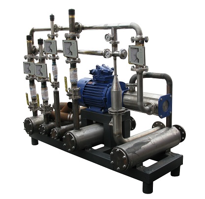
The additive, coming to the power plant, is unloaded into special tanks, where actual operating solution is prepared. The solution is then directed to special storage tanks for liquid additive. From these tanks, a portioner pumps the liquid through filters to second stage HFO pumps (with ejection type blenders).

Some of the widely used additives are based on Mg, Mn and Al dispersed in oil.


Pressurizing the fuel before combustion

Pressure of liquid fuel is selected based on the required dispersal of the fuel for a given nozzle efficiency. Pressure of HFO before the nozzles is chosen based on the required nozzle power. Fuel pressure before the nozzles can be low (less than 0.7 MPa), medium (less than 3.5 MPa) and high (over 3.5MPa). The required pressure is reached by using pumps of various types and purposes.

Gear pumps are used to pump HFO colder than 80°С and are used as circulation and main pumps in industrial boilers; feed from 0.22 to 9m/hour, pressure 0.6 to 2.5MPa.

Screw pumps (three screws) are used to pump HFO colder than 100°С at various HFO facilities or industrial boilers as main pumps; feed 0.45 to 6.84 m3/hour, pressure 2.5 to 4 MPa.

Centrifugal pumps are designed for pumping of HFO colder than 80°С and are used at thermal power plants as main pumps and first raise pumps, feed 35 to 560 m3/hour, pressure 0.7 to 3.7 MPa.

Heating HFO before nozzles

Before injecting liquid fuel into the boiler, it is heated for proper viscosity. The temperature of heating is defined by type of HFO and atomization method (see table1).

Table 1

HFO heating temperature before nozzles, °С

HFO type

Mechanical nozzles

Steam mechanical nozzles

Rotary and steam atomization nozzles

100

150 (135)

125

100

100 В

125

115

40

120

110

90

40 В

110

100

F

80

80


Steam goes to HFO heaters (Fig 2, pos 7) from turbine bleed or directly from the boiler at 1.6Mpa at up to 300°С (saturated or somewhat overheated).

Figure 5 shows the design of a double pipe heater, used in HFO facilities.

Fig. 1.5. Double pipe HFO heater.


Atomization of liquid fuel and creation of fuel-air mixture.

These stages are critical in fuel preparation for combustion. Quality of atomization and mixture creation directly influences economy and reliability and the combustion process in various modes of operation. Atomization of liquid fuel is done in nozzles, fuel and air mixture is created in burners of various types and designs.

The main nozzle types used in energy production are mechanical and nozzles with atomization media. Mechanical atomization involves pushing the fuel through a small orifice (1…3 mm) at significant pressure (1.0…2.0 MPa). The atomizing part of a centrifugal nozzle (head) is shown in Figure 6. It consists of three main components. In the disk 4, the fuel is separated into small streams, in the disk 5 the stream vortices are created, and the fuel is atomized in the nozzle inset 6.


Figure 6. Mechanical nozzle head: 1 – head inset; 2 – stop nut; 3 – covering nut; 4 – distribution disk; 5 – vortex disk; 6 – nozzle inset.


Steam or air kinetic energy cause atomization in steam or pneumatic nozzles. E.g. in stream nozzles as shown in Figure 7, HFO is atomized by direct influence by steam kinetic energy and ejection.

Figure 7. Stream nozzle: 1 – plug; 2 – gasket; 3 – atomizer; 4 – steam collector; 5 – body; 6 – fuel shaft; 7 – steam shaft.


Steam and pneumatic/mechanical nozzles atomize fuel by simultaneous influence of both mechanical and stream (pneumatic) swirlers. Such nozzles are double-shaft (atomization agent influences the fuel when the fuel exits the nozzle into the furnace (Fig.8) or double-shamber (streams of fuel and atomization agent interact inside the nozzle) with one outlet.

Figure 8. Steam/mechanical nozzle head: 1 – covering nut; 2 – distribution washer; 3 – fuel swirler; 4 – steam swirler.


In rotary nozzles fuel is atomized and ejected into the furnace by rotating cylinder (Figure 9). The fuel enters the nozzle through hollow pipe, then to the wall of the cylinder, where it is distributed as film, which cuts off at the cylinder’s edge. Additional air (10…20% of combustion air) is fed to the glass to further influence the fuel film. The rich mixture of air and fuel drops enters the furnace.

Combustion efficiency depends on atomization quality, which is characterized by the droplet size distribution, mean droplet diameter, spray angle, stream range and stream concentration, i.e. the amount of liquid passing through a unit of stream cross-section area in a unit of time.

Fractional constitution of drops in the stream may be presented as a normal Gaussian distribution dependency.

Figure 9. Rotary nozzle head: 1- fuel feed pipe; 2- hollow rotating shaft; 3 – body; 4 – feeder; 5 – rotating atomization cylinder; 6 – air swirler.

Figure 10. Drop distribution frequency curve.

Graphical representation is shown in Figure 10. The curve demonstrates that drop size distribution is quite uneven.

Fuel additives. To add or not to add?

If high quality winter diesel is in short supply, the pour point depressants and anti-gel additives can indeed simplify operation of diesel vehicles in winter. However, things are never that simple. First of all, any additive, be it anti-gel or depressant, is a preventive measure and has no effect on the fuel post-factum, when the contents of the fuel tank has already separated, or worse, became a cream like substance. There are no simple ways to reanimate frozen engine, so no attempts should be made to kick-start the motor. It is far better to find a warm garage. Second, the efficiency of winter additive operation is depends a lot of the quality of the original fuel, and there is no guarantee that the same additive makes an equal positive impact on diesel from BP and diesel in a farm tractor. The third and last point to consider is that anti-gels and depressants modify only solved paraffins, therefore the actual effect requires that the additive be introduced into warm fuel. Summer fuel cloud point (the beginning of paraffin crystal precipitation) is -5°С. To give the depressant a chance, the temperature of the fuel when adding the depressant should be at least 10°С higher than that, otherwise it will have no result. But how can a vehicle owner warm up the fuel, beside putting the canister on a stove?

So, catch 22? Well, yes, in a sense. However, the risk to fill the tank with “frozen” fuel is significantly lower when filling up at large fuel stations. Such stations usually store the fuel in large underground tanks, which are naturally (ground) or artificially insulated. The diesel fuel in such tanks cools down relatively slowly, goes into the fuel supply line relatively warm and may well be suitable for additives. On the other hand, the probability of getting summer fuel instead of winter fuel is quite a bit lower at large fuel stations, which belong to companies which try to maintain the quality of the fuel supplied. At the same time, there is never too much of a good thing, and the winter additives will do no harm to winter fuel. The question is more of a cost effectiveness, which must be judged against the risk of getting summer fuel in winter.


By the way…

Compact electric heater in fuel inlets and fine filters are a serious competition to chemical additives.

Keep the following in mind:

– increased additive content past the max effective concentration has no effect on improvement of fuel cold weather performance;

– putting an additive into cloudy diesel is pointless, since the additive only influences dissolved paraffins;

– between fuel freezing point and filtration temperature, the latter is the more important parameter;

– a depressant can lower the minimum diesel temperature by no more than 10 degrees;

– quality of the diesel is a serious factor in additive efficiency;

Additive sample No

Recommended concentration

Low temperature performance

Diesel-fuel pour point, °С

Minimum filtration point, °С

Source fuel

-16

-6

1

354 ml/50 l

-28

-19

2

245 ml/150 l

-34

-29

3

355 ml/75 l

-28

-16

4

25 ml/10 l

-27

-19

5

355 ml/75 l

-26

-16

6

355 ml/75 l

-28

-15

7

886 ml/500 l

-29

-17

8

150 ml/50 l

-27

-17

9

354 ml/378 l

-26

-15

10

1 ml/1 l

-25

-16

11

354 ml/50 l

-33

-17

12

125 ml/40 l

-23

-14

13

100 ml/100 l

-24

-14

14

1 l/284 l

-34

-21

15

325 ml/100 l

-32

-17

16

444 ml/135 l

-34

-20

Diesel fuel standard requirement

below -25’С

below -15°С

un → ru
in

SUMMER FUEL TO WINTER FUEL without psychic powers: is it possible?

The subject of this article is neither industrial production of the valuable winter fuel in USB type blending and compounding systems, not a new cheat method. Simply imagine a truck driver who still has summer diesel when cold weather hits. Of course, drivers usually have some way to warm the fuel, such as torches, heaters etc, but it still requires a lot of effort. Just how much effort, depends on the situation.

Time for some optimism. There are special antigel diesel fuel additives, specifically designed to increase its cold weather performance. As usually, we selected several samples of such material for our tests. These are STP Diesel Anti Gel, K&W Anti Gel, Jet go Diesel Fuel Conditioner, Wynn’s Ice proof for diesel and “Aspect-Modifier”. Such a representative range was assembled not as much to select the best or the worst one, but to fully present the products currently in the market.

As outside temperature drops, diesel fuel goes through three stages: first it clouds, then it reaches the so called filtration point and then, finally, it becomes solid.

Cloud point signifies the beginning of gel formation out of the paraffin hydrocarbons in the fuel. This temperature has not changed much with the addition of the products to summer fuel (see table below). It is as it should be, because depressor additives do not dissolve paraffins and do not reduce their amount, instead, paraffins are bound and do not form large clots. Filter clog point is the next important milestone. Problems start when paraffin clots starts to containate the filters. The last column in the table is the temperature when diesel stops flowing: it is a kinf od theoretical indication of the fuel’s operational limit.

So what do the test show? If summer fuel’s filter point is -7°С, adding the “correct” additive drops it to -10°С. Pour point drops from -13* to -22-29°С. Not bad. “Correct” means that not only recommended concentration must be observed, but also mixing temperature. That is, the additive should be administered beforehand, while it is still warm and paraffin sedimentation has not yet started.

Two important considerations:

First, such additives cannot turn summer fuel to “real” winter fuel (pour point -35°С).

Second, the effect of the additives declines with temperature. Therefore, an attempt to turn winter fuel to arctic fuel will be less effective than in our experiments, with no more than 3 – 5 degree gain. By the way, the numbers are not absolute. Additive effectiveness depends on fuel composition, which is defined by crude material and production process.

Another way to combat diesel fuel settling is adding kerosene or gasoline into it. These two can solve some of the paraffins hydrocarbons. Can this method be used in combination with additives described above? Turns out, it can. Some of the paraffins will be dissolved by kerosene, while some will be bound by the additive. The total effect, unfortunately, will be less impressive than expected. There is no way of turning summer diesel into arctic diesel with the above methods. It can only be done by more efficient industrial processes.

Oil blending systems – it is not a blockbuster, it’s business

The chief objective of any business is to increase profits by reducing expenses and maximizing productivity. The technology market is constantly developing. The important thing is to make engines to operate with more reliability, efficiency and better fuel economy. It is also worth remembering that engine efficiency is much dependant on fuel quality. Traditional fuels, regular gasoline, manifest three factors which influence the result: envonmental, consumption and entirely unpredictable. Call it ECU. This ECU factors are detrimental to the objective of any business, that is, profit maximization. Environmental pollution, costs of fuel quickly consumed and the entirely unpredictable repair costs incurred by filter clogging, formation of soot etc.

Blending systems are widely used around the world for mixing of various components to produce the fuel which is most suitable in terms of intended use and production costs.

The USB blending systems is one of GlobeCore Blending trade mark brands. These systems are designed for blending of several fuel components, such as biodiesel fuel with regular diesel, low octane gasoline with various components etc. Such blending systems are capable of increasing cetane or octane number of the fuel and increase fuel storage life to beyond 180 days.

The USB blending systems are fully stand alone equipment, fitted with a pump, an electric motor, valves and flow meters. Components may be blended in any ratio depending on client recipe.

If a solution exists for many technological problems, it is worth considering. The blending systems are one of the ways to protect the business from ECU factors and to increase competitiveness in any market.

Fuel compliant with European standards made with USB petroleum blending systems

One of the main debates of today are environmental problems. The detrimental effect of modern heavy industry on the environment and resource consumption lead to one effect: depletion of resources. In the over-industrialized society, lack of fuel for machinery and vehicles is a point of crises.

The currently known fuels (gasoline and diesel) become a breaker for many businesses. Environment emission reduction and increasing of production efficiency at minimal cost are important factors for manufacturing business owners and CEOs.

Annual increase of oil production and consumption has a direct effect on the environment. Introduction of new costly environmental technologies are only cost-effective in the long run. One of the solutions, long since used in such energy powerful nations as US, Denmark or France, is the use of blending systems, which mix various types of fuels for optimal final blend.

In the new conditions, fuel is made based on various additives, for instance, alcohol (ethanol or methanol), or natural oils. Blending of various fuels increases efficiency of internal combustion engines. It also rarely requires significant changes to equipment.

One of the more important issues is the selection of optimal components for fuel blends. Components vary from the most volatile (butane) to the least volatile (crude) to obtain 10 – 15 specific parameters of the future fuel.

To make fuel of the required quality and class, blending systems for liquid components are used. GlobeCore’s offer are the USB blending systems for mixing of fuel blends. The system can mix up to six components and additives.

These systems are designed for various industries. Custom designed systems may be installed indoors or outdoors under canopy or may be made mobile.

The USB type blending units by GlobeCore are used all over the world for blending of various fuels. The pure form of fuel with the use of tar or gasoline is less efficient and causes more emissions to the atmosphere.

The advantages of blending systems are ease of operation, high blending rate, perfect quality of the finished products, capability of blending many components, as well as long storage life of the finished product. The USB type compounding systems by GlobeCore the fuel blends can be made compliant with European standards, the objective of many domestic companies, business competitiveness can be increased and profit obtained not based on economy, but on efficient operation of your equipment.

«Alcohol» blending – a future without gas haze

In the beginning of the new millennium, after the virtual “rise of the machines”, increased attention is paid to conservation of resources. Many developed nations, such as the US, Germany and Japan, who depend on fuel imports, have launched a serious effort of resource diversity development. The main ideas of how to make machines run without the regular fuel were the use of electricity, propane, fuel cells, biodiesel fuel, ethanol or methanol. Each has advantages and drawbacks. The main advantage of alcohol, such as methanol, in combination with gasoline is that alcohol is a renewable resource and the supply is virtually unlimited.

Methanol is also referred to as wood spirit. The performance of methanol mixes makes them a choice for both internal combustion engines and special fuel cells for generation of electricity. In 2013, one of the leading fuel cell manufacturers, Ballard Power Systems, announced the launch of reserve electric power supply systems. The product is used in communications and the performance increase reliability and service life, while keeping maintenance and repairs simple. Methanol is also used for production of gasoline for sports cars. An engine running on methanol works longer than one running on regular gasoline, and its power increase by as much as 20% with the same cylinder volume.

A particular characteristic of using methanol with gasoline is the small difference of heat generation during combustion of both components. Methanol’s higher vaporization heat improves volumetric efficiency, reducing heat stress. Therefore, an alcohol-air mix burns better. Hence the 10-15% power increase with less fuel consumption.

Methanol is also the most suitable fuel for large scale industrial production. It is worth noting that the market for methanol, which is produced from a wide range of feedstocks, is quite extensive. The world leaders in these technologies are BioMCN (The Netherlands), Blue Fuel Energy (Canada), Carbon Recycling International (Iceland), Chemrec (Sweden), Enerkem (Canada), and VärmlandsMetanol (Sweden).

GlobeCore’s compounding systems are designed to use methanol as a high octane additive to improve performance of gasoline and reduce its environmental impact. Besides, the use of methanol decreases formation of engine sludge. Cost of methanol is lower than that of gasoline and it does not require readjustment of engines.

Using hydrodynamic blending system made by GlobeCore allows to reduce production time and required operator labor force. The product is customizable. Therefore in the future you will be able to fully control processing, compounding and the use of fuel.

New petroleum recipe – shaken, not stirred

New technologies develop as rapidly as market  demand dictates. In the global environmental battle, companies attempt to protect themselves from the attention of the environmentally and save on resources as well. Alternative fuels for industrial equipment and machinery have been around for some time now. The key of this innovation is the ability to mix and blend various components to make a cleaner and better fuel. The use of compounding systems allows production of efficient fuel which in turn enhances engine operation.

There is a significant difference between blending and mixing systems. In theory, the missing process implies two components. For instance, mixing diesel fuel with biodiesel improves the smoothness of fuel combustion in the engine. Blending process is a bit more complicated. To endow fuel with certain properties, various oils and additives can be used. Blending of various less expensive components produces the same result as finished high quality fuel product, but at a lower cost.

Every model of the GlobeCore’s blending system range can blend from 2 to 10 components. Individual adjustment and system programming is optional on customer request.

Compounding units and blending system feature a high processing capability and guarantee production of high quality fuel with long storage life.

Blending systems used in oil and gas industry, are very important. One of the products of oil refining, oil tar is used as oil fuel. However, corrosion, difficult stirring and high viscosity make this fuel less than ideal in terms of efficiency and reliability. Still, combining oil tar with gasoline and certain additives in a compounding system, it is possible to produce a higher quality gasoline, which increases efficiency of internal combustion engines and is less damaging to component parts.

GlobeCore offers a large selection of USB type blending systems, each with its own characteristics. However, in the end, the main advantage of such systems is increased efficiency of engines running on blended fuel, longer life time, differentiation of fuel supplies and additional savings on fuel resources.